The Approximately Monthly Zoomer
Hardware Hacking 2: Electric Boogaloo
2024-05-10
After dabbling in hardware hacking last time, I think I might have found my most recent passion. I’m switching to an ISP that allows you to have any router of your choosing attached, so I thought I could find one with OpenWrt support and install it for maximum customization. The router should support the IEEE standards 802.11ax and ac for the newer clients on the network and also n for internet of shit and legacy devices from hell (also known as “printers”). Also, it should be somewhat future-proof, support the latest stable branch of OpenWrt, and not break the bank. This lead me to the Asus RT-AX59U, which received OpenWrt support in November of 2023.
Git Blame
At the time of writing the OpenWrt wiki page for this router was lacking to say the least - the only information as to how to install OpenWrt onto the router was the commit message of the commit that added support for it. The general idea was this:
- Set up a TFTP server with the intramfs firmware that is reachable by the router.Section 4
- Connect to the router via UART.
- Interrupt the boot sequence to get to a shell.
- Download the intramfs image over TFTP and boot it.
- Use sysupgrade to install OpenWrt permanently.
Sounds a little complicated but more than doable, so I went ahead and bought the router for 100 gold, fully confident I could do it. It all worked out fine in the end but I did encounter some unexpected problems.
Is this thing glued?
There are only two screws that are visible from the outside - they
are located on the underside of the device, holding the base attached to
the device. So I went ahead and unscrewed them. 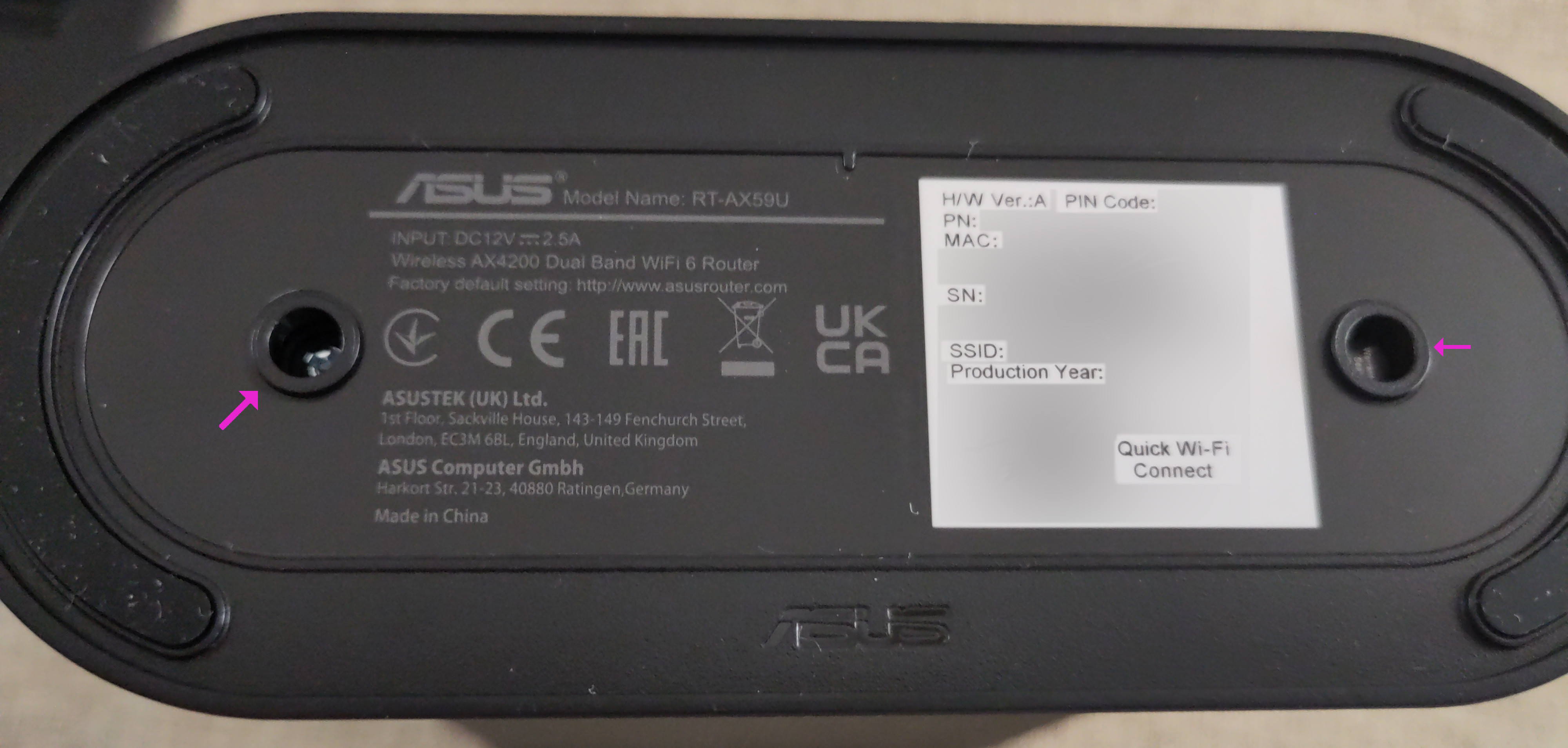 I expected the base to fall off or at least be
easy to remove, but the amount of force I had to use to remove it lead
me to believe I missed some pin I had to push down or some hidden button
I had to press. Sure, breaking the base would have been suboptimal, but
I could have easily 3D-printed some sort of base if I broke it, so I
went ahead and pulled like a maniac. The next two screws were somewhat
hidden deep inside the enclosure, but nothing you can’t reach with a
regular screwdriver.
 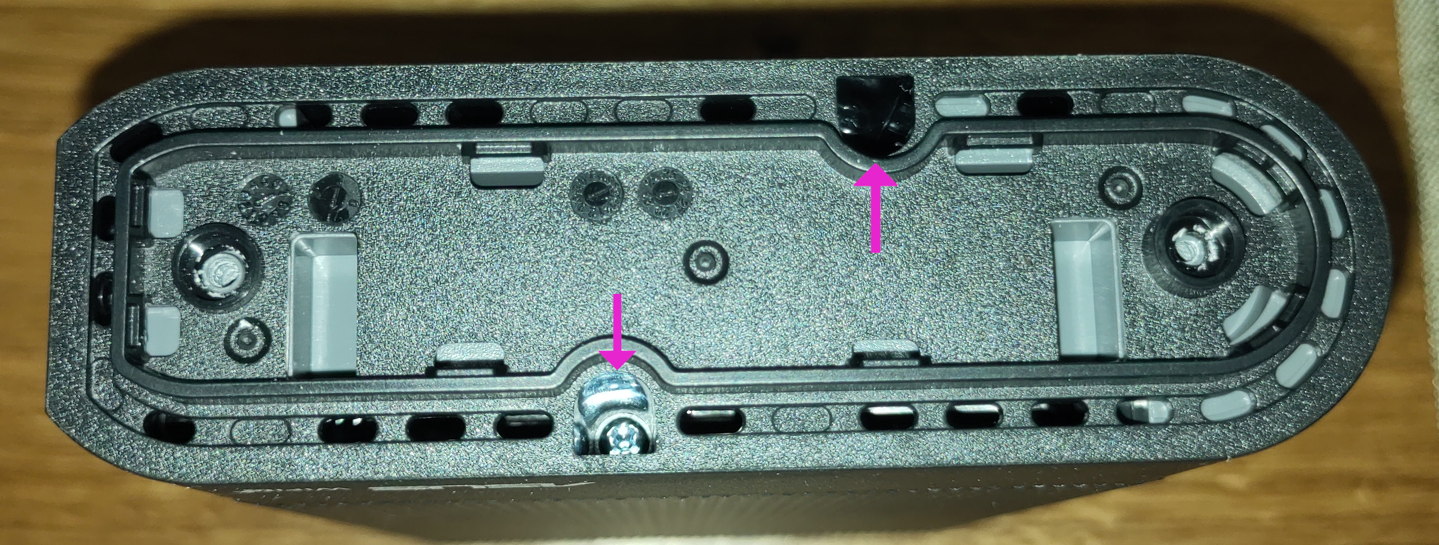 With those
removed, I again tried to pry away another layer. It was so hard to pull
away that I had to ask someone else for help - both grasping the router
with both hands and pulling it apart. A rather cartoonish scene, but it
worked. I wasn’t sure how to proceed from here and pull away even more
of its plastic casing but I didn’t need to since I already found what I
needed.
UART
After removing the plastic, you immediately get greeted by four
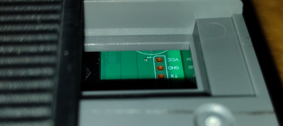
unpopulated pins. 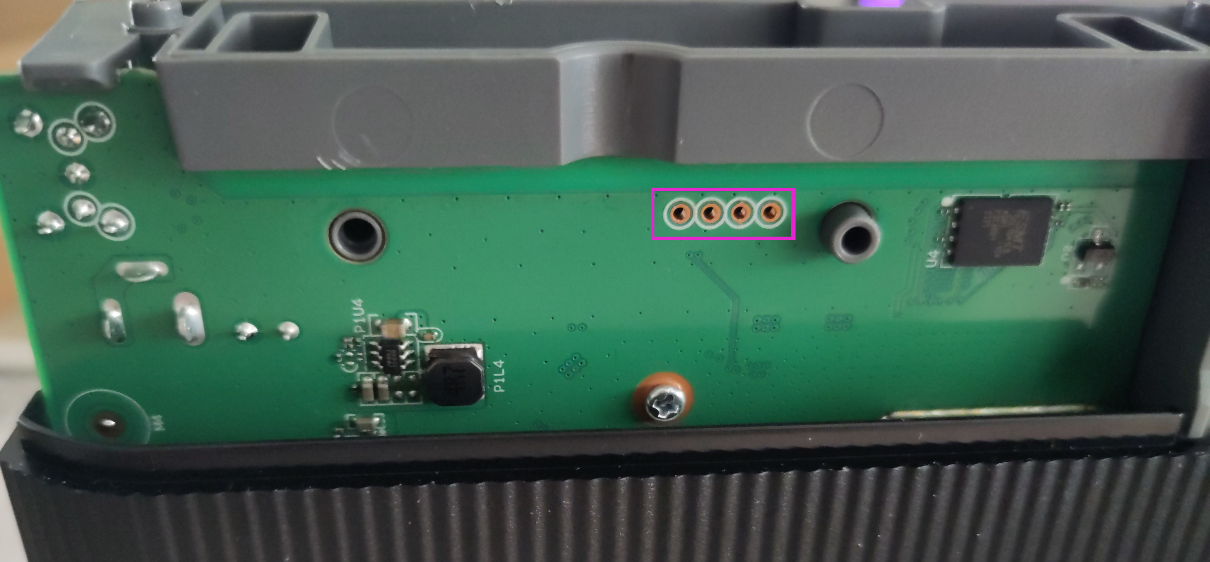 On the other side, that is visible through a
small window, we can see that the pins are labelled “RX, TX, GND, VCC”.
 Before plugging in a USB TTL adapter, I quickly
checked the baud rate with my oscilloscope. This step wasn’t really
necessary since modern devices are pretty much always™ communicating at
115200 baud with 8 data bits,
no parity bits and 1 stop bit - you’ll
also see this referred to as
 115200,8N1. Now that we know
where to plug in and which parameters to use we can go ahead and attach
the cables to the router, plug in the USB cable into a computer on one
end, on the other end we enthusiastically plug into a micro USB port
and…
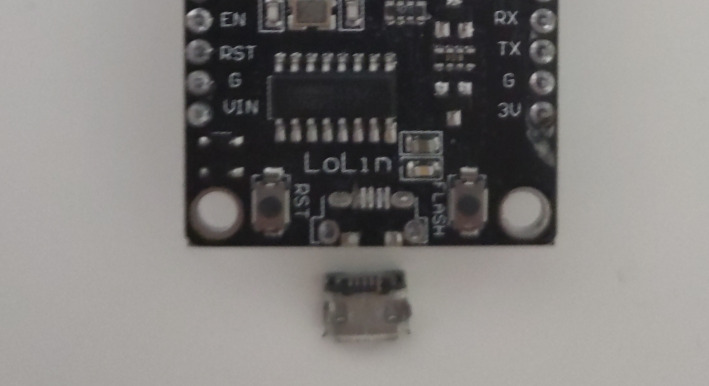
…break it.
Enshittification of Local Business
I try to have all tools I need ready when starting with a project,
because when I start, I really don’t want to stop. Unfortunately there
weren’t any local businesses that sell USB TTL converters for a
reasonable price. 30 gold for a CH340-based adapter? No thank you!
Suddenly I became very creative and remembered that I have a raspberry
pi somewhere, so I bought a coffee instead and headed home. The
raspberry pi has a lot of GPIO pins, surely some of them can be used for
UART. Checking some docs we can see that this is indeed the case. Pins 14 and 15 can be used
after running raspi-config and enabling the serial console
in the interfaces section (disable login shell, enable serial port).
Intermediate Egyptology 201
After waiting for what felt like an eternity for the raspberry pi to
boot I was greeted by the minimal raspberry pi os desktop environment.
The first thing I did was enable ssh and connect it to my network, so I
wouldn’t have to directly interact with it. Within ssh I ran
picocom -b 115200 -r -l /dev/serial0, started the router,
and got nothing but garbled output with the occasional readable text. So
garbled in fact, that it messed with my shell and turned it into a
display of ancient Egyptian linguistics. It couldn’t have been the wrong
baud rate, I checked with my oscilloscope and there wouldn’t have been
entire blocks of text that are readable. I double and triple checked
that all pins were properly connected and had good contact and thought
that maybe the ssh connection was wonky. Maybe it works on the raspi but
doesn’t get sent over ssh properly. When I entered the command on the
raspi it was still garbled - but it was less garbled! Success!
When I saw it was still garbled, but less so, it immediately
clicked. The raspberry pi is overloaded and can’t keep up with Wi-Fi,
bluetooth, ssh, a desktop environment, and UART at the same time! I
disabled Wi-Fi and bluetooth, dropped down to the login shell with
Ctrl + Alt + F2 (or was it F3? I don’t remember) and
finally got ungarbled output.
Inspecting the Shell
We can interrupt the boot sequece by pressing the number
(1|2|3|4|7|9) at the right time.
Please choose the operation:
   1: Load System code to SDRAM via TFTP.
   2: Load System code then write to Flash via TFTP.
   3: Boot System code via Flash (default).
   4: Entr boot command line interface.
   7WAN Show April 19, 2024: Load Boot Loader code then write to Flash via Serial.
   9: Load Boot Loader code then write to Flash via TFTP.

You choosed 4

   4: Entr boot command line interface.

U-Boot 2022.04-rc1 (Aug 02 2023 - 10:59:04 +0800)
MT7986>
I choosed [sic] 4 to enter the U-Boot shell and then proceeded to download the OpenWrt intramfs image.
MT7986> setenv ipaddr 192.168.1.1
MT7986> setenv serverip 192.168.1.70
MT7986> tftpboot 0x46000000 rtax59u.bin
switch prereq:0
Using ethernet0@15100000 device
TFTP from server 192.168.1.70; our IP address is 192.168.1.1
Filename 'rtax59u.bin'.
Load address: 0x46000000
Loading: Got ARP REPLY, set eth addr (e1:ee:78:00:81:e5)
#################################################################
     #################################################################
     #################################################################
     #################################################################
     #################################################################
     #################################################################
     #################################################################
     #########################################
     12.6 MiB/s
done
Bytes transferred = 7278084 (6f0e04 hex)
MT7986>
Now we should be able to boot the downloaded image.
MT7986> bootm 0x46000000
## Loading kernel from FIT Image at 46000000 ...
And after a while, we are greeted with this beautiful ascii art:
BusyBox v1.36.1 (2024-03-22 22:09:42 UTC) built-in shell (ash)

  _______                     ________        __
 |       |.-----.-----.-----.|  |  |  |.----.|  |_
 |   -   ||  _  |  -__|     ||  |  |  ||   _||   _|
 |_______||   __|_____|__|__||________||__|  |____|
          |__| W I R E L E S S   F R E E D O M
 -----------------------------------------------------
 OpenWrt 23.05.3, r23809-234f1a2efa
 -----------------------------------------------------
root@OpenWrt:/#
Now we can login to the webinterface, install the sysupgrade image, reboot, bob’s your uncle.
No Screwing Around
Usually these kinds of products have some sort of tamper evident warranty sticker somewhere. I only realized where it was when I was reassembling it - it was on one of the screws of the second set removed.
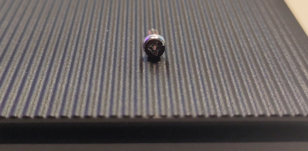
But don’t worry about these stickers because in most countries the manufacturers can’t actually weasel their way out of a warranty replacement unless they can prove that you broke the device. Funnily enough, I didn’t even put these screws back in since they are not in contact with any metal (so are not used for grounding) and the clips of the plastic case are strong enough to hold up a person, let alone the case itself.
